
Ball Mill Design Handbook Pdf
Pdf Design And Fabrication Of Mini Ball Mill Part 2. Http Www Bicoinc Com Assets Ballmill Operatingmanual Pdf. Ball Mill Design Handbook Pdf Kaser Vtngcf Org. Circulating Load Calculation Formula. Ball Mill Design Power Calculation. Mechanical Milling A Top Down Approach For The Synthesis Of. Chapter 5 Track Components And Materials Track
 WhatsAppGet PriceGet A Quote
Ball Mill Design Handbook Pdf
Pdf Design And Fabrication Of Mini Ball Mill Part 2. Http Www Bicoinc Com Assets Ballmill Operatingmanual Pdf. Ball Mill Design Handbook Pdf Kaser Vtngcf Org. Circulating Load Calculation Formula. Ball Mill Design Power Calculation. Mechanical Milling A Top Down Approach For The Synthesis Of. Chapter 5 Track Components And Materials Track
WhatsAppGet PriceGet A Quote
Milling Equations
Milling Equations Machining Time : Peripheral Milling T m = L + A f r T m = Machining Time (Min.) L = Length of Cut A = Approach Distance f r = Feed Rate (Dist./ Min.) Machining Time : Face Milling T m = f r L + A + O T m = Machining Time (Min.) L = Length of Cut A = Approach Distance O = Cutter Run Out Distance f r = Feed Rate (Dist./ Min.) 4
WhatsAppGet PriceGet A Quote
GMSG GUIDELINE: DETERMINING THE BOND EFFICIENCY OF INDUSTRIAL
closing screen for the ball mill test one (standard square root of 2 series) mesh size coarser than the plant ball mill circuit P80. If between standard mesh sizes, the finer of the chose two. Results of Bond ball mill tests conducted with closing screens of 75 µm or finer are to be treated with caution. The
WhatsAppGet PriceGet A Quote
MODELING THE SPECIFIC GRINDING ENERGY AND BALL-MILL SCALEUP
Ball mill power draw predicted from the Denver slide rule, kW 0 200 400 600 Calculated ball-mill power draw from the m odel derived, kW Data compared Line y=x Fig. 2. Comparison of the ball mill power draw from the Denver slide rule and the proposed model. Dashed line corresponds to y=x.
WhatsAppGet PriceGet A Quote
Design, Construction and Performance Analysis of a 5
laboratory ball mill. This method is based on two power calculation approaches used in ball and rod mill design processes due to its simplicity and workability. The first approach, which is specific power calculation, determines the power required to grind an ore from a given feed size to a specific product size. The second approach, the shaft
WhatsAppGet PriceGet A Quote
Design Method of Ball Mill by Sumitomo Chemical Co., Ltd
on ball motion in mills using the discrete element method has been proposed by Mishra et al.2) and Yanagi et al.3) So far, reports on analyses simulat-ing three-dimensional analysis and complex liner shapes,4), 5)and research on mill power consump-tion 6), 7) have been published. However, most of them are concerned with the simu-
WhatsAppGet PriceGet A Quote
How Ball Mills Work (Engineering and Mining)
Learn how a ball mill works, all of its main parts and some of its design features! This 3D animated video allows you to see all the internal parts of a ball...
WhatsAppGet PriceGet A Quote
EFFECTS OF GRINDING MEDIA SHAPES ON BALL MILL PERFORMANCE
Figure 5.11 Power variation with mill speed for different media shapes (J=15%).86 Figure 5.12 Power variation with mill speed for different media shapes (J=20%).87 Figure 5.13 Power variation with mill speed for different media shapes (J=25%).87 Figure 5.14 Variation of mill power draw with mill filling, J (cylpebs media)…..88
WhatsAppGet PriceGet A Quote
MODELING THE SPECIFIC GRINDING ENERGY AND BALL-MILL SCALEUP
Ball mill power draw predicted from the Denver slide rule, kW 0 200 400 600 Calculated ball-mill power draw from the m odel derived, kW Data compared Line y=x Fig. 2. Comparison of the ball mill power draw from the Denver slide rule and the proposed model. Dashed line corresponds to y=x.
WhatsAppGet PriceGet A Quote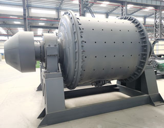
EFFECT OF BALL SIZE DISTRIBUTION ON MILLING PARAMETERS
2.6.1 Ball size distribution in tumbling mills 37 2.6.2 Milling performance of a ball size distribution 40 2.7 Summary 41 Chapter 3 Experimental equipment and programme 43 3.1 Laboratory grinding mill configuration 43 3.2 Preparation of mono-size grinding media 44 3.3 Feed material preparation 46
WhatsAppGet PriceGet A Quote
Ball Mill Working Principle And Main Parts
Ball Mill Working Principle. To be chosen according to the grinding material, material is composed of a ball mill feed end of the hollow shaft is arranged in the tube body, when the ball mill cylinder rotation time, grinding body due to inertia and centrifugal force, the effects of friction, making it attached to the cylinder liner on the cylinder body away, when taken to the height of a
WhatsAppGet PriceGet A Quote
Ball Milling
ball milling Ar c Franziska Schneider, Org. Proc. Res. & Develop., 2009, 13,44 Up to 96% yield Entry Rpm T (min) Yield% 1 400 10 92 2 800 5 94 .
WhatsAppGet PriceGet A Quote
Design, Construction and Performance Analysis of a 5
laboratory ball mill. This method is based on two power calculation approaches used in ball and rod mill design processes due to its simplicity and workability. The first approach, which is specific power calculation, determines the power required to grind an ore from a given feed size to a specific product size. The second approach, the shaft
WhatsAppGet PriceGet A Quote
A Method of C alculating Autogenous/ Semi-Autogenous Grinding
mills with the rod mill and ball mill laboratory work indices. Note, in Figure. 1, that the rod mill product slope is less than 0.5 due to an extra amount of nes present being fi fi ner than 650 μm. These fi nes proceed to the ball mill improving the ball mill effi ciency. Also, the plotted rod mill P80 value, as shown in Figure 1, is 2900
WhatsAppGet PriceGet A Quote
Ball Milling
ball milling Ar c Franziska Schneider, Org. Proc. Res. & Develop., 2009, 13,44 Up to 96% yield Entry Rpm T (min) Yield% 1 400 10 92 2 800 5 94 .
WhatsAppGet PriceGet A Quote
A Method of C alculating Autogenous/ Semi-Autogenous Grinding
mills with the rod mill and ball mill laboratory work indices. Note, in Figure. 1, that the rod mill product slope is less than 0.5 due to an extra amount of nes present being fi fi ner than 650 μm. These fi nes proceed to the ball mill improving the ball mill effi ciency. Also, the plotted rod mill P80 value, as shown in Figure 1, is 2900
WhatsAppGet PriceGet A Quote
TECHNICAL NOTES 8 GRINDING R. P. King
mill is the energy consumption. The power supplied to the mill is used primarily to lift the load (medium and charge). Additional power is required to keep the mill rotating. 8.1.3 Power drawn by ball, semi-autogenous and autogenous mills A simplified picture of the mill load is shown in Figure 8.3 Ad this can be used to establish the essential
WhatsAppGet PriceGet A Quote
MILLING CONTROL & OPTIMISATION
Mill Feed(t/h) & Load(t) 300 1800. Power(kW) 250 200 150 100 50 0 1600 1400 1200 1000 800 600 400 200. MillStar OFF MillStar ON. Mill Overloads Mill Feed Cuts DAY 1 DAY 2 DAY 3 DAY 4 Mill Feed PV Mill Feed SV Mill Load Power. Figure 7: Mill Power Optimisation results for Case Study 1 Figure 8: Mill Power Optimisation results for Case Study 2
WhatsAppGet PriceGet A Quote
GEAR COUPLINGGEAR COUPLING
N-2 Order Today ! Phone / Fax / Visit / www.powerdrive.com GEAR COUPLING Coupling Selection... Based on Equivalent hp Ratings Table2 1010G 1015G 1020G 1025G 1030G 1035G 1040G 1045G 1050G 1055G 1060G 1070G
WhatsAppGet PriceGet A Quote
Ball Mill Design/Power Calculation
The basic parameters used in ball mill design (power calculations), rod mill or any tumbling mill sizing are; material to be ground, characteristics, Bond Work Index, bulk density, specific density, desired mill tonnage capacity DTPH, operating % solids or pulp density, feed size as F80 and maximum ‘chunk size’, product size as P80 and maximum and finally the type of circuit open/closed
WhatsAppGet PriceGet A Quote
Ball Mills
8.3.2.2 Ball mills. The ball mill is a tumbling mill that uses steel balls as the grinding media. The length of the cylindrical shell is usually 1–1.5 times the shell diameter ( Figure 8.11). The feed can be dry, with less than 3% moisture to minimize ball coating, or slurry containing 20–40% water by weight.
WhatsAppGet PriceGet A Quote
Orway Mineral Consultants Canada Ltd. Mississauga, ON., L4W
80 sizes typically reached by conventional ball milling. The delineating size between coarse and fine grinding is 750 µm. SMC test results are used to determine the Drop Weight Index (DWi) and the coarse ore grinding index (M ia). Test data from the Bond ball mill work index test is used to calculate the fine grinding index (M ib). The M ia and M
WhatsAppGet PriceGet A Quote
TECHNICAL NOTES 8 GRINDING R. P. King
mill is the energy consumption. The power supplied to the mill is used primarily to lift the load (medium and charge). Additional power is required to keep the mill rotating. 8.1.3 Power drawn by ball, semi-autogenous and autogenous mills A simplified picture of the mill load is shown in Figure 8.3 Ad this can be used to establish the essential
WhatsAppGet PriceGet A Quote
Milling Equations
Milling Equations Machining Time : Peripheral Milling T m = L + A f r T m = Machining Time (Min.) L = Length of Cut A = Approach Distance f r = Feed Rate (Dist./ Min.) Machining Time : Face Milling T m = f r L + A + O T m = Machining Time (Min.) L = Length of Cut A = Approach Distance O = Cutter Run Out Distance f r = Feed Rate (Dist./ Min.) 4
WhatsAppGet PriceGet A Quote
EFFECT OF BALL SIZE DISTRIBUTION ON MILLING PARAMETERS
2.6.1 Ball size distribution in tumbling mills 37 2.6.2 Milling performance of a ball size distribution 40 2.7 Summary 41 Chapter 3 Experimental equipment and programme 43 3.1 Laboratory grinding mill configuration 43 3.2 Preparation of mono-size grinding media 44 3.3 Feed material preparation 46
WhatsAppGet PriceGet A Quote
Design Method of Ball Mill by Sumitomo Chemical Co., Ltd
on ball motion in mills using the discrete element method has been proposed by Mishra et al.2) and Yanagi et al.3) So far, reports on analyses simulat-ing three-dimensional analysis and complex liner shapes,4), 5)and research on mill power consump-tion 6), 7) have been published. However, most of them are concerned with the simu-
WhatsAppGet PriceGet A Quote
Bond Grinding Circuit Efficiency
Mill Ball Mill Closed circuit crushing to 16 mm Open circuit 8’ dia. rod mill to 1 mm Closed circuit 8’ dia. ball mill to P80 um The ore Test Work Index = Circuit Operating Work Index 9 The Standard Bond Circuit Coarse Ore Bins Fine Ore Bins Screen Crushing Screen Classification Rod Mill Ball Mill THIS IS THE REFERENCE BASIS FOR ALL WORK
WhatsAppGet PriceGet A Quote


 Mecca 500TPH Granite Crushing Plant