181 Process Flow Diagram (PFD) Symbols for Engineers
There are a number of standards related to process flow diagrams in industry, to ensure adequate representation of engineering systems. The most common standards are: ISO 15519-1:2010(en): Specification for diagrams for the process industry — Part 1: General rules
 WhatsAppGet PriceGet A Quote
Chapter 6. Data-Flow Diagrams
Data-flow diagrams (DFDs) model a perspective of the system that is most readily understood by users – the flow of information through the system and the activities that process this information. Data-flow diagrams provide a graphical representation of the system that aims to be accessible to computer specialist and non-specialist users alike.
WhatsAppGet PriceGet A Quote
schematic flowsheet for purification of silica, combining
Based on composition, the glass was formulated by adding an average 10.0 mass% of CaCO3 and 5.0 mass% of Na2CO3 to 35.0 mass% of SiO2, which resulted in the production of a green-coloured glass.
WhatsAppGet PriceGet A Quote
Appendix I
Appendix I - Fruit and vegetable processing flow-sheets. Contents - Previous - Next. GROUP 1.1 SIMPLE PROCESSING. PROCESSING OF MANGO BARS. Processing of mango bars. Ripe fruit is used; the mangos are washed, peeled and cut into pieces with a stainless steel knife.
WhatsAppGet PriceGet A Quote
diagram for glass sheet plate crusher
diagram for glass sheet plate crusher – Grinding Mill . diagram for glass sheet plate crusher Strongly recommend you to contact with us through online service! Meanwhile, you will get a appropriate discount! » Learn Morediagram for glass sheet plate crusher | Solution for Mining Quarry glass crusher machine in India. Get Price
WhatsAppGet PriceGet A Quote
29.7 TITLE OF DOCUMENT: PROCESS FLOW DIAGRAMS (PFD) and
A) Process flow diagram is a fundamental process drawing which depicts major process related equipment, machines, and process lines in a simple manner. Inputs for generating process flow diagram are as follows: – Design basis – Simulation Report – Thermo-physical property data. i) The contents of process flow sheets are mainly as follows:
WhatsAppGet PriceGet A Quote
Piping & Instrument Diagrams
(adapted from Kauffman, D., Flow Sheets and Diagrams. ChE 4253
Industry Advisors, Investors, Customers, Licensing Partners February 18, 2016 Cost Modeling 5. Sheet 1: Process Diagram Block Flow Diagram / Bill of Materials Process Flow Diagram / BOM + rough scematic Process Simulation / Computer Aided Design
WhatsAppGet PriceGet A Quote
The Float Process Step by step
The melting process is key to glass quality; and compositions can be modified to change the properties of the finished product. Stage 2: Float bath Glass from the melter flows gently over a refractory spout on to the mirror-like surface of molten tin, starting at 1,100°C and leaving the float bath as a solid ribbon at 600°C.
WhatsAppGet PriceGet A Quote
Flowchart
Flow Chart Symbols. You''ll notice that the flowchart has different shapes. In this case, there are two shapes: those with rounded ends represent the start and end points of the process and rectangles are used to show the interim steps.
WhatsAppGet PriceGet A Quote
Glass industry worldwide
Indeed, the market value of the glass packaging industry worldwide is expected to grow from 51.23 billion U.S. dollars in 2020 to 69.25 billion U.S. dollars by 2027. This text provides general
WhatsAppGet PriceGet A Quote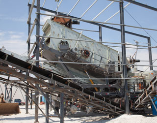
Formulations and Manufacturing Process of
Personal care industry in India is very huge and is one of the plant layout & process flow sheets. The Major Contents of the book are phenyl, floor cleaner, glass cleaner, toilet Process Flow Diagram of Floor Cleaner 4. Glass Cleaner Uses & Applications Properties of Glass Cleaner
WhatsAppGet PriceGet A Quote
Float Glass Process
The float glass process, which was originally developed by Pilkington Brothers in 1959 (Haldimann et al., 2008), is the most common manufacturing process of flat glass sheets.More than 80–85% of the global production of float glass is used in the construction industry (Glass for Europe, 2015a).In the float glass process, the ingredients (silica, lime, soda, etc.) are first blended with
WhatsAppGet PriceGet A Quote
AP-42, CH 12.20: Electroplating
This section addresses the electroplating industry. However, emphasis is placed on chromium Figure 12.20-3 presents a flow diagram for a typical chromic acid anodizing process. Types of shield materials used are herculite glass, wire safety glass, neoprene, and vinyl chloride polymers.
WhatsAppGet PriceGet A Quote
RAW MATERIAL FLOW CHART | Creately
RAW MATERIAL FLOW CHART. Use Creately’s easy online diagram editor to edit this diagram, collaborate with others and export results to multiple image formats. You can edit this template and create your own diagram. Creately diagrams can be exported and added to Word, PPT (powerpoint), Excel, Visio or any other document.
WhatsAppGet PriceGet A Quote
AIS Glass
Glass Manufacturing Process. Have you ever wondered how is glass made? The glass – float glass as we know – is manufactured by the PPG process. This process was invented by Sir Alistair Pilkington in 1952 and is the most popular and widely used process that describes how to make glass for architectural purposes in the world today.
WhatsAppGet PriceGet A Quote
11.16 Gypsum Manufacturing
A flow diagram for a typical gypsum process producing both crude and finished gypsum products is shown in Figure 11.16-1. In this process gypsum is crushed, dried, ground, and calcined. Not all of the operations shown in Figure 11.16-1 are performed at all gypsum plants. Some plants
WhatsAppGet PriceGet A Quote
The Float Process Step by step
The melting process is key to glass quality; and compositions can be modified to change the properties of the finished product. Stage 2: Float bath Glass from the melter flows gently over a refractory spout on to the mirror-like surface of molten tin, starting at 1,100°C and leaving the float bath as a solid ribbon at 600°C.
WhatsAppGet PriceGet A Quote
Glass industry 4th year: varieties of Glass and flow sheet
chemistry 4th year
WhatsAppGet PriceGet A Quote
schematic flowsheet for purification of silica, combining
Based on composition, the glass was formulated by adding an average 10.0 mass% of CaCO3 and 5.0 mass% of Na2CO3 to 35.0 mass% of SiO2, which resulted in the production of a green-coloured glass.
WhatsAppGet PriceGet A Quote
Piping & Instrumentation Diagrams Guide | Lucidchart
Instrumentation detail varies with the degree of design complexity. Simplified or conceptual designs are called process flow diagrams (PFDs). A PFD shows fewer details than a P&ID and is usually the first step in the design process–more of a ’s eye view. More fully developed piping and instrumentation diagrams (P&IDs) are shown in a P&ID.
WhatsAppGet PriceGet A Quote
Glass & Glazing Contractors in the US
Glass & Glazing Contractors in the US industry trends (2016-2021) Glass & Glazing Contractors in the US industry outlook (2021-2026) poll Average industry growth 2021-2026 : x.x lock Purchase this report or a membership to unlock the average company profit margin for this industry.
WhatsAppGet PriceGet A Quote
Glass manufacturing
8. The manufacture of glass is in four phases: (1) preparation of raw material, (2) melting in a furnace, (3) forming and (4) finishing. 10. Flat glass, sheet glass, or plate glass is made by two processes. The processes are float glass process and rolled glass process. 11.
WhatsAppGet PriceGet A Quote
P&ID Symbols (Complete List & PDF)
ISA SYMBOLOGY. The symbology for the identification of the measurement and control instrumentation on the flow and process diagrams and on the P&ID (Piping & Instrument Diagram), commonly called P&I (Piping & Instrumentation), is generally compliant with the Standard ISA (Instrumentation Society of Automation) identified as S.5, that is composed of identification codes and graphic symbols.
WhatsAppGet PriceGet A Quote
The Dynisco Extrusion Processors Handbook
SECTION 2: MATERIALS AND THEIR FLOW Glass Transition Temperatures (T g) and Melting Temperatures (T m) for Some Thermoplastic Used in the home and industry for appliances, for electric power distribution, communications etc. • Profile: Used for tracks, windows,
WhatsAppGet PriceGet A Quote
RAW MATERIAL FLOW CHART | Creately
RAW MATERIAL FLOW CHART. Use Creately’s easy online diagram editor to edit this diagram, collaborate with others and export results to multiple image formats. You can edit this template and create your own diagram. Creately diagrams can be exported and added to Word, PPT (powerpoint), Excel, Visio or any other document.
WhatsAppGet PriceGet A Quote
Engineering Standards Manual: Standard Drawings & Details
Sheet Rev. PDF CAD Title Date; EXAMPLE DRAWINGS ---M6010-0: See Chapter 8 I&C Series D6000 Series: Process Flow Diagram Tower, DI, and Chilled Water : M6020-0: Process Flow Diagram HVAC : M6030-0: Piping & Instrumentation Diagram HVAC : M6040-0: Piping & Instrumentation Diagram Tower, DI, & Chilled Water : M6041-0: Piping & Instrumentation
WhatsAppGet PriceGet A Quote
Flow Chart Examples
ISO 9001:2000 Level II Flow Charts Printed 11/17/04 9:10 PM Page 2 2002 Cayman Business Systems Rev: Release Print: Wednesday, November 17, 2004 Elsmar.com Example Flow Charts Slide 2 A diagram that uses graphic symbols to depict the nature and flow of the steps in a process Flowchart Benefits of Using Flowcharts • Promotes understanding of a
WhatsAppGet PriceGet A Quote-
How to Manufacture Glass: Glass Manufacturing Process
The roller helps the molten glass to spread in the form of a thin sheet. (iv) Pressing: In this process, the molten glass is pressed into moulds. The pressure may either be applied by hand or by mechanical means. This process is adopted for ornamental articles, hollow glass articles etc.
WhatsAppGet PriceGet A Quote 
Glass production
Flow point 6.6 7.6 An annealing oven (known in the industry as a lehr) heats the container to about 580 °C (1,076 °F), Float glass is a sheet of glass made by floating molten glass on a bed of molten metal, typically tin, although lead and various low melting point alloys were used in the past. This method gives the sheet uniform
WhatsAppGet PriceGet A Quote
Process Flow Diagrams (PFDs) and Process and Instrument
Process flow diagrams (PFDs) are used in chemical and process engineering. These diagrams show the flow of chemicals and the equipment involved in the process. Generally, a Process Flow Diagram shows only the major equipment and doesn''t show details. PFDs are used for visitor information and new employee training.
WhatsAppGet PriceGet A Quote


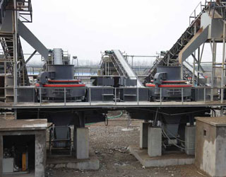
 Mecca 500TPH Granite Crushing Plant